

How To Draw A A10 Thunderbolt

American
I inquire that the moderators read carefully the suggestion of the A-ten Thunderbolt Ii, give thanks you for the attention

A-10 Thunderbolt Ii

The A-10 Thunderbolt II, affectionately nicknamed "The Warthog," was adult for the United states of america Air Force by the OEM Team from Fairchild Republic Visitor, now a part of Northrop Grumman Corporation Aerospace Systems Eastern Region located in Bethpage NY and St. Augustine FL. Following in the footsteps of the legendary P47 Thunderbolt, the OEM Team was awarded a study contract in the 1960s to define requirements for a new Close Air Support aircraft, rugged and survivable, to protect combat troops on the footing. This initial report was followed up by a prototype evolution contract for the A-10, and a final flyoff competition resulting in the selection of the A-10 Thunderbolt Two
The A-ten was built-in of the Attack-Experimental (A-X) program office, which launched in 1966 to develop a basis-attack aircraft to supersede the Douglas A-1 Skyraider.
In 1970, the threat posed by the Soviet Union's overwhelming number of tanks along the borders of Western Europe led the Air Force to request contractor proposals for an airframe specifically designed to bear the CAS mission and destroy enemy armor.
The call for designs stipulated a low-price aeriform weapons platform – less than $3 million per unit – capable of loitering above the battlefield and engaging enemy targets at low altitude and speed with a high-speed rotary cannon, while providing farthermost coiffure and aircraft survivability.
Later, the requirements would be further specified to include a maximum speed of 450mph and a normal operating speed of 300mph in combat to enable easier engagement of ho-hum moving ground targets.
Furthermore, the new aircraft was required to take off in less than 4,000 feet, enabling operations from small airfields close to the front lines, carry an external load of 16,000 pounds and have a mission radius of 285 miles, all for a final cost of $1.four meg per shipping.
Of the vi proposals submitted to the Air Force, Northrop and Fairchild Republic were selected to build prototypes.
Specific ground rules were established by the Air Force to ensure off-white competition during the competitive prototype stage. Operation goals were established by the Air Force Headquarters, and revisions to those goals could only upshot from joint contractor SECAF-appointed console discussions. There was to be no advice between the contractors, and the SPO would provide equal distribution of information to them. The contractors were authorized to initiate design changes they accounted necessary as long as these changes were in the context of the specifics of the contracts.The Air Force designated the two contractor'southward designs as the A-9A (Northrop) and A-10A (Fairchild)

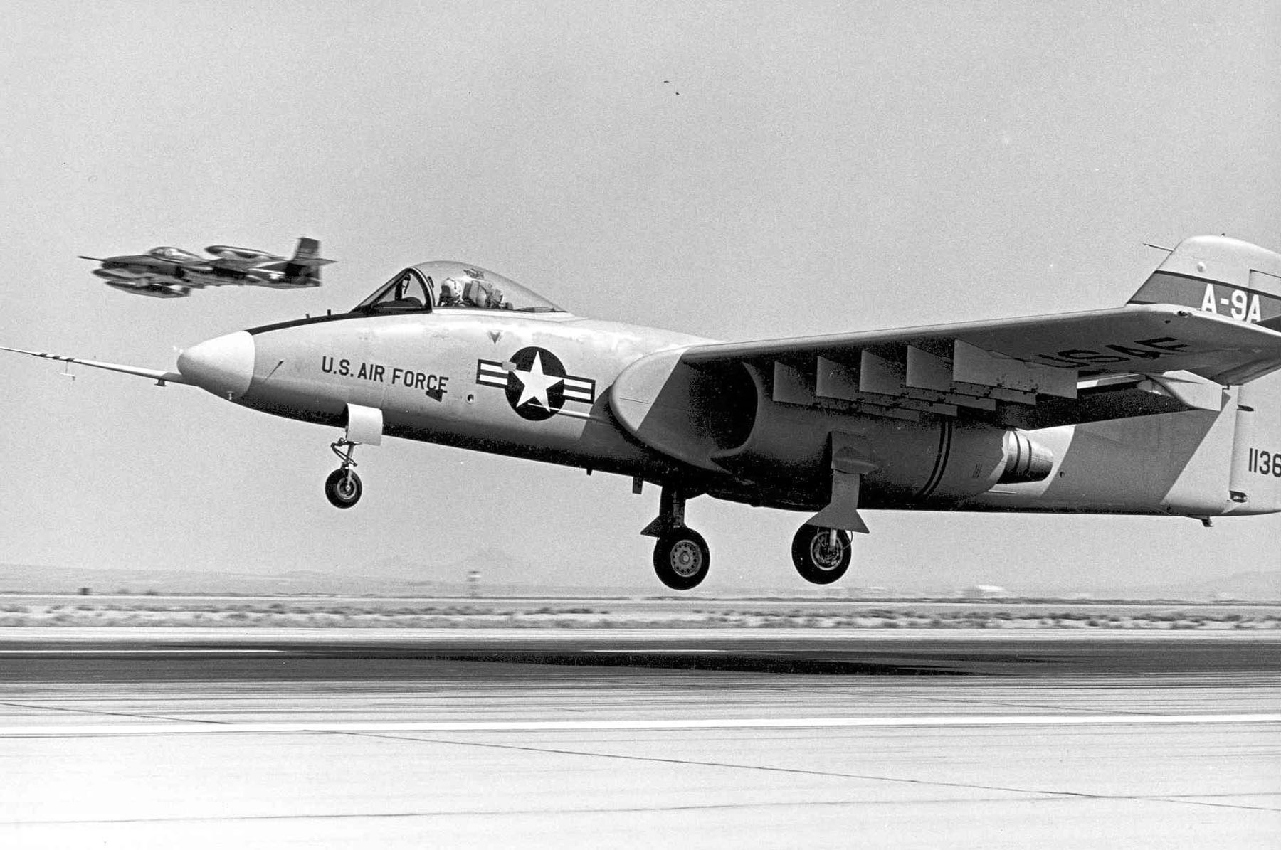
The Prototypes The A-9A was a twin turbofan aircraft using the non-afterburning YF102 engines rated at 7500 lbs of thrust per engine.It was a high wing design with the engines located under the wing root adjacent to the fuselage (run across Figure thirteen.) The lower thrust YF102 engine cost less than the TF34, just the lower thrust required an increase in wing spanto meet the low-speed maneuvering and take-off distance requirements.xxivThe design-to-price goals were evident not just in the selection of the lower cost engine, but in the option of off-the-shelf equipment such every bit the main landing gear struts from the McDonnell Douglas A-4, wheels and brakes from the Grumman Gulfstream 2, olfactory organ landing gear from the Northrop A-5, and ejection seat from the McDonnell Douglas Southward-3A. Further evidence of attention paid to production price was the utilize of interchangeable left and right side parts for engines, control surfaces, and other parts.
Spoiler

Survivability features of the A-9A included redundant critical structural members, admission doors designed to blow out in the event of an internal explosion, redundant hydraulic flight controls with manual dorsum-up, foam filled and selfsealing fuel tanks, and a "bathtub" of armor plating effectually the cockpit. Maintenance features included breast high engine placement for ease of basis-level service; Northrop engineers speculated that an engine replacement could exist accomplished in 30 minutes.
Northrop YA-9

Figure 13. The YA-9A Paradigm
Spoiler

The Northrop YA-9 was a prototype attack aircraft adult for the The states Air Strength A-Ten programme. The YA-9 was passed over in preference for the Fairchild Commonwealth YA-10 that entered product equally the A-10 Thunderbolt 2.
Spoiler

Northrop YA-9A, the get-go flight of the shipping occurred on May 30, 1972. USAF
Background: Criticism that the U.S. Air Force did not take close air support seriously prompted a few service members to seek a specialized attack aircraft. In the Vietnam State of war, large numbers of ground-attack aircraft were shot down by small artillery, surface-to-air missiles, and low-level anti-aircraft gunfire, prompting the evolution of an shipping meliorate able to survive such weapons. Fast jets such as the North American F-100 Super Sabre, Republic F-105 Thunderchief, and McDonnell Douglas F-iv Phantom Ii proved for the virtually part to be ineffective for close air back up. The Douglas A-i Skyraider was the USAF's primary close air back up aircraft.
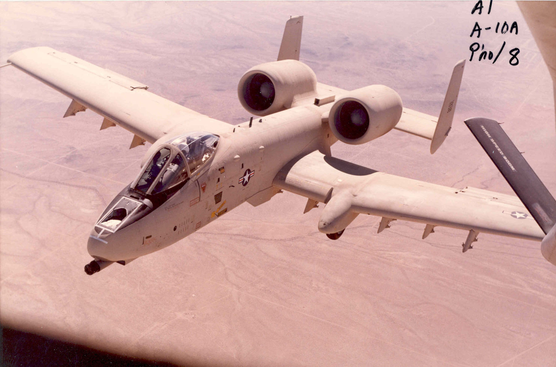
YA-10A Prototype

Fairchild Republic YA-10A (Southward/North 71-1370) in flight. (U.S. Air Force photo)
The A-10A was also a twin-engine turbofan design, with the biggest difference between information technology and the A-9A being the placement of the wing and engines, and the tail configuration (see Figure 14.) The TF34 was a non-afterburning turbofan rated at over ix,000 lbs of thrust, and the engines were placed above and behind the wing in pods attached to the outside of the fuselage. The high placement of the engines reduced the chance of Foreign Object Harm (FOD) during take-off and landing, and likewise enabled rapid mission plow effectually on the ground as the engines could be left running while rearming. The rearward placement of the engines reduced the IR signature as the frazzle from the engine was partially shielded from view past the tail. The low fly allowed for ease of store loading, and as well immune wing mounted landing gear for a wider rails and better stability on rough forrad area landing strips.Fairchild also used interchangeable left and right side parts for cost control. Survivability features included redundant hydraulic flight controls with mechanical redundancy, a titanium "bathtub" around the cockpit, twin vertical stabilizers, foam filled self sealing fuel tanks, and main landing gears that partially protruded from nacelles on the wings making gear-up landing less hazardous. "The aircraft is designed to fly with ane engine, 1 tail, i elevator and half a fly torn off."
Effigy xiv. The YA-10A Prototype.

Presentation of the 1st epitome of Fairchild Democracy A-10A (Series No. 71-1369) / USAF
On 10 August 1972, the Air Force released proposal instructions for the continued evolution and testing of the CAS aircraft. Each of the contractors submitted technical and cost proposals in October 1972 which were to be used with the results of the competitive fly-off to select the single contractor that would get forward with advanced evolution.
Competitive Wing-offs and Shoot-offs The YA-10A made its first flight on 10 May 1972, approximately 17 months after contract award. The YA-9A made its first flying x days afterward. (See Figures 15, sixteen.)
Between May and October 1972 the contractors flying tested their shipping, accumulating 162 hours on the YA-9A and 190 hours on the YA-10A. The fly-off between the two shipping was conducted at Edwards AFB, CA betwixt 10 Oct and ix Dec 1972. "During this period the A-9A crews flew 123 sorties for a full of 146 flight hours and the A-10A was flown 87 sorties for a total of 138.v flight hours."Both aircraft utilized an internal M61 20mm Gatling Gun in place of the developmental GAU-8/A which was not ready for testing. The fly-off was intended to task the aircraft with difficult flight atmospheric condition in order to magnify the differences in blueprint. While not a chief goal of the fly-off, weapon commitment accuracy was evaluated and both aircraft were institute to perform adequately with only minor differences between them.
Effigy 15. YA-9A Flight Examination
Spoiler
Northrop YA-9A, the first flight of the aircraft occurred on May 30, 1972. USAF
Figure xvi. The YA-10A on Landing
Spoiler

Moments before landing at Edwards Air Base at the finish of the 1st flying on May 10, 1972, with Fairchild Republic examination pilot Sam Nelson in control. / USAF

Front end view of the 1º prototype Fairchild Republic YA-10A (Serial No. 71-1369), armed, showing the provisional General Electrical M61A1 "vulcan", 20mm. Observe the lateral displacement of the landing gear, a necessary feature to enable the installation of the cannon in the nose of the aircraft. / USAF


1º prototype of the Fairchild Commonwealth A-10A (Serial No. 71-1369) during a test flying. / USAF
Shortly after the competitive A-Ten fly-off, the GAU-viii/A "shoot-off" between GE and Philco Ford began.The gun competition was conducted at Eglin AFB from 3 January to 6 April 1973. Air Force evaluation teams fired and maintained the guns, with contractors acting only in an advisory capacity. Each contractor supplied three guns (two for evaluation, one for backup and spare parts) and 100,000 rounds of Target Do ammunition.The programmed test called for 70,000 rounds to exist fired for each design – 35,000 rounds each for the two guns supplied for testing by each contractor. The GE supplied guns fired over lxx,000 rounds, but the Philco Ford guns fired less than 16,000 rounds due to repeated jamming.The GE guns averaged viii,800 rounds between failure, while the Philco Ford guns averaged only 728.The GE pattern met or exceeded the performance expectations in all areas except weight. The gun weight increased from 367 to 591 lbs, and the total arrangement weight from 2607 to 3885. Despite this weight growth, the GE pattern was declared operationally suitable and GE was declared the winner of the prototype competition.
GE handily trounce Philco Ford in the GAU-eight/A competition, but withal had to wait forconclusion of the test firings of the Oerlikon 304RK gun (designated the GAU-9/A). The Oerlikon gun didn't fare much meliorate than the Philco Ford design. Tabular array x shows the comparison of the examination results for the GAU-8 and GAU-nine gun contest. The GAU-eight numbers correspond to the GE designed system. The DSARC reviewed the GAU-eight/A program on 5 June 1973 and recommended proceeding with full-calibration development of the gun and armament. On 21 June GE was awarded a fixed-toll-incentive-fee contract for approximately $24M. The contract was to deliver seven preproduction gun assemblies and to refurbish the three prototype guns. GE was also responsible for the evolution and limited production of a family unit of 30mm ammunition. One of the provisions of the contract approval was that GE bring on a second subcontractor for ammunition development. Already teamed with Aerojet for ammunition development, GE subcontracted with Honeywell to provide a 2d source. Honeywell was well positioned to do this every bit they were subcontracted to Philco Ford for the competitive prototype evolution stage. The toll of the second source for the ammunition development was $17M in RDT&E.

Performance Comparison of the GAU-eight/A and GAU-9/A


Comparison between the size of a Full general Electric GAU-eight / A Avenger cannon with a Protrude. The Avenger weighs 281 kg and is 6.06m long.
The General Electric GE GAU-8/A Avenger is a 30 mm hydraulically driven 7-butt Gatling-type autocannonthat is typically mounted in the United states Air Force'due south Fairchild Commonwealth A-10 Thunderbolt II. Designed specifically for the anti-tank function, the Avenger delivers very powerful rounds at a high rate of burn down. The GAU-viii/A is too used in the Goalkeeper CIWS ship weapon organization, which provides defense against brusque-range threats such as highly maneuverable missiles, aircraft and fast maneuvering surface vessels.

The General Electric GAU-eight / A Avenger is the most powerful cannon e'er installed on a tactical plane, around which the A-x was practically built. The installation of the huge 30mm piece at the front of the shipping, tilted downwards by two degrees, required larmer displacement of the front landing gear. Rarely has a unmarried weapon been so of import to a fighter airplane.


Spoiler


Precision: 80% of rounds fired at iv,000 feet (1,200m) range striking within a forty-foot (12m) diameter circle
Ammo:
PGU-14/B API Armor Piercing Incendiary (DU)
PGU-13/B HEI High explosive incendiary
PGU-15/B TP Target Practice
Armor penetration of Armor-Piercing Incendiary ammunition, BHN-300 RHA, assault bending 30 degrees from vertical:
76mm at 300 meters
69mm at 600 meters
64mm at 800 meters
59mm at i,000 meters
55mm at i,220 meters
On January 18, 1973, the USAF selected the Fairchild Commonwealth aircraft as winner of the A-X. In June of the same year, General Electric was selected to manufacture the GAU-8 Avenger

1º prototype of the Fairchild Republic YA-10A (serial number 71-1369), on Dec 18, 1974, during a test flight near Edwards Air Base of operations, armed with 28 MK-82 bombs / National Archive, Washington DC
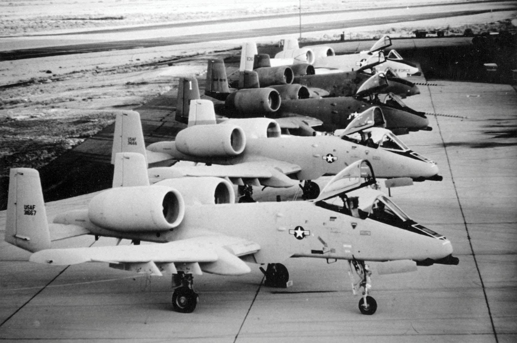
Production
The first A-10 production thunderbolt II flew in late 1975. In 1976, the 333th tactical Fighter Training Squadron, belonging to the 335 tactical Fighter Traning wing of Tactical Air Control, received the first A- at the base of Davis-Monthan, Arizona . the starting time squadron to use the A-10s fabricated information technology operational in late 1977. counting the two prototypes and half-dozen pre-series aircraft, only 721 units were built, the last of which was delivered to the USAF in March 1984.
Spoiler


A: Two General Electric TF34 turbofans power the A-10 and are high-mounted in pods to the rear of the aircraft to avert debris when using rough airstrips.
B: In its original 'tank-busting' role the A-10'southward main weapon was the General Electric GAU-8/A Avenger 30mm 7-barrelled Gatling-type Cannon.
C: For the FAC office the OA-10 carries few weapons apart from 2 rocket pods for target marking and AIM-9 Sidewinder air-to-air missiles.
D: The main undercarriage retracts forward into an underwing bay. In theory, once the aircraft's weapon load has been dropped, a safe wheels upward landing can be made with minimal fly damage.

Spoiler


Spoiler

Spoiler

Spoiler

A-10A instrument panel

Gimmicky friend of the A-10 Thunderbolt Two is Sukhoi Su-25
Comparing ordnance; Left: Sukhoi Su-25 "Frogfoot" Correct: A-10 "Thunderbolt-Ii"


Comparison ordnance; Left: Sukhoi Su-25 "Frogfoot" Right: A-10 "Thunderbolt-Two"

Specifications (A-10 Thunderbolt Two)
Spoiler
General characteristics
Crew:i
Length: 53 ft 4 in (16.26 1000)
Wingspan: 57 ft six in (17.53 chiliad)
Height: 14 ft 8 in (4.47 m)
Wing area: 506 ft² (47.0 yard²)
Airfoil: NACA 6716 root, NACA 6713 tip
Empty weight: 24,959 lb (11,321 kg)
Loaded weight: 30,384 lb (13,782 kg)
CAS mission: 47,094 lb (21,361 kg)
Anti-armor mission: 42,071 lb (19,083 kg)
Max. takeoff weight: 50,000 lb (23,000 kg)
Internal fuel chapters: 11,000 lb (4,990 kg)
Powerplant: 2 × General Electric TF34-GE-100A turbofans, 9,065 lbf (twoscore.32 kN) each
Performance
Never exceed speed: 450 knots (518 mph, 833 km/h) at five,000 ft (ane,500 m) with 18 Mk 82 bombs
Maximum speed: 381 knots (439 mph, 706 km/h) at sea level, clean
Cruise speed: 300 knots (340 mph, 560 km/h)
Stall speed: 120 knots (138 mph, 220 km/h)
Combat radius: CAS mission: 250 nmi (288 mi, 460 km) at 1.88 hour loiter at 5,000 ft (1,500 m), 10 min combat
Anti-armor mission: 252 nmi (290 mi, 467 km), 40 nmi (45 mi, 75 km)) bounding main-level penetration and leave, 30 min combat
Ferry range: ii,240 nmi (2,580 mi, 4,150 km) with 50 knot (55 mph, 90 km/h) headwinds, 20 minutes reserve
Service ceiling: 45,000 ft (13,700 m)
Charge per unit of climb: half dozen,000 ft/min (xxx k/southward)
Fly loading: 99 lb/ft² (482 kg/m²)
Thrust/weight: 0.36
Ammunition
Guns: 1×30mm (one.eighteen in) GAU-viii/A Avenger rotary cannon with ane,174 rounds (chapters 1,350 rd)
Hardpoints: 11 (8× under-wing and 3× under-fuselage pylon stations) with a capacity of 16,000 lb (7,260 kg) and provisions to carry combinations of:
Rockets: 4× LAU-61/LAU-68 rocket pods (each with 19×/7× Hydra 70 mm/APKWS rockets, respectively) 6x LAU-131 rocket pods (each with 7x Hydra 70 rockets)
Missiles: 2× AIM-9 Sidewinder air-to-air missiles for cocky-defence force half-dozen× AGM-65 Maverick air-to-surface missiles
Bombs: Mark 80 series of unguided fe bombs or Mk 77 incendiary bombs or BLU-1, BLU-27/B, CBU-twenty Rockeye Two, BL755[197] and CBU-52/58/71/87/89/97 cluster bombs or
Paveway series of Laser-guided bombs or Joint Direct Attack Munition (JDAM) (A-10C) or Wind Corrected Munitions Dispenser (A-10C)
Other: SUU-42A/A Flares/Infrared decoys and crust dispenser pod or AN/ALQ-131 or AN/ALQ-184 ECM pods or Lockheed Martin Sniper XR or LITENING targeting pods (A-10C) or
2× 600 US gal (two,300 Fifty) Sargent Fletcher drib tanks for increased range/loitering fourth dimension.
source:
Edited past pieve

Source: https://forum.warthunder.com/index.php?/topic/417726-a-10-thunderbolt-ii/
Posted by: waterswittionfer93.blogspot.com
0 Response to "How To Draw A A10 Thunderbolt"
Post a Comment